Creo Parametric :-
 |
Creo Parametric Software is also a part of CAD drawing , it is similar to AutoCAD mechanical Autodesk 2020 and is used in mechanical field for creating 3D models of tools , dies , blocks , etc . It has some modifications which makes it more user friendly to create 3D drawings easily with less effort. It has more precision and accuracy as compared with AutoCAD for generating 3D models. Creo Parametric is a certified and official product of PTC .
How to use Creo Parametric :-
In this I'm gonna give you some helpful tips and tricks on using Creo,One of the first things we need to do before we get started is make sure we have the right hardware. In this case, a mouse with a middle scroll wheel. If you don't have one, it's actually really important that you do to use Creo,so see if you can find one. All right, if you have your own files that's absolutely fine. In this case, we're gonna show you where you can get some files from our "How to model almost anything." curriculum if you don't have files of you own. We actually keep all our how to model almost anything files available for you on official website, ptc.com/academic-program/student.So, if you're on that page, scroll down to the very bottom, and here on the bottom left, you'll see how to model almost anything. If you click on that,it'll start a download. You can save those files to your desktop, or your downloads folder and we'll go from there as soon as you unzip them. So now that we have downloaded our files, one of the first things we need to do is select the working directory. This is actually important. So Creo doesn't know where to find your files when you first open it. You have to tell it what folder you want to look in, and that's what setting our working directory is. If we don't set a working directory, Creo has no way of finding the projects, or assemblies, or parts that we want to work with. To find our working directory, what we do, is we open up Creo, and you'll see in the top left, there's several options that we can work with. From new, over to open,select working directory, which is the option that we want, and then some other options, that if we're changing between projects we would use but we're not going to touch right now. So we're gonna click select working directory, and by default your working directory is the public documents folder. So if you were to open up Creo, and just start working,that's where all your items would be saved and where it would look by default.Click our desktop because that's where I saved my project folder. We're gonna go how to model almost anything, and then we're gonna pick a sub folder that has one of the assemblies that we want to work with. I'm gonna pick cool bike, and then from there if we hit OK, you'll see in the bottom left hand corner here, successfully changed the working directory to our cool bike. So we're good to go from there. Now once we have our working directory set, we're ready to actually open up our files and use them. So to do that, with our working directory set, we're going to hit open, and you'll see the folder that it's looking for, is exactly what we set it to, cool bike. So from there I'm gonna pick this cool bike top assembly. Open it up. And there we go. So when we open up apart or assembly in Creo, there's actually two representations that we'll see on screen. The first one here, is the actual graphical building of the assembly.
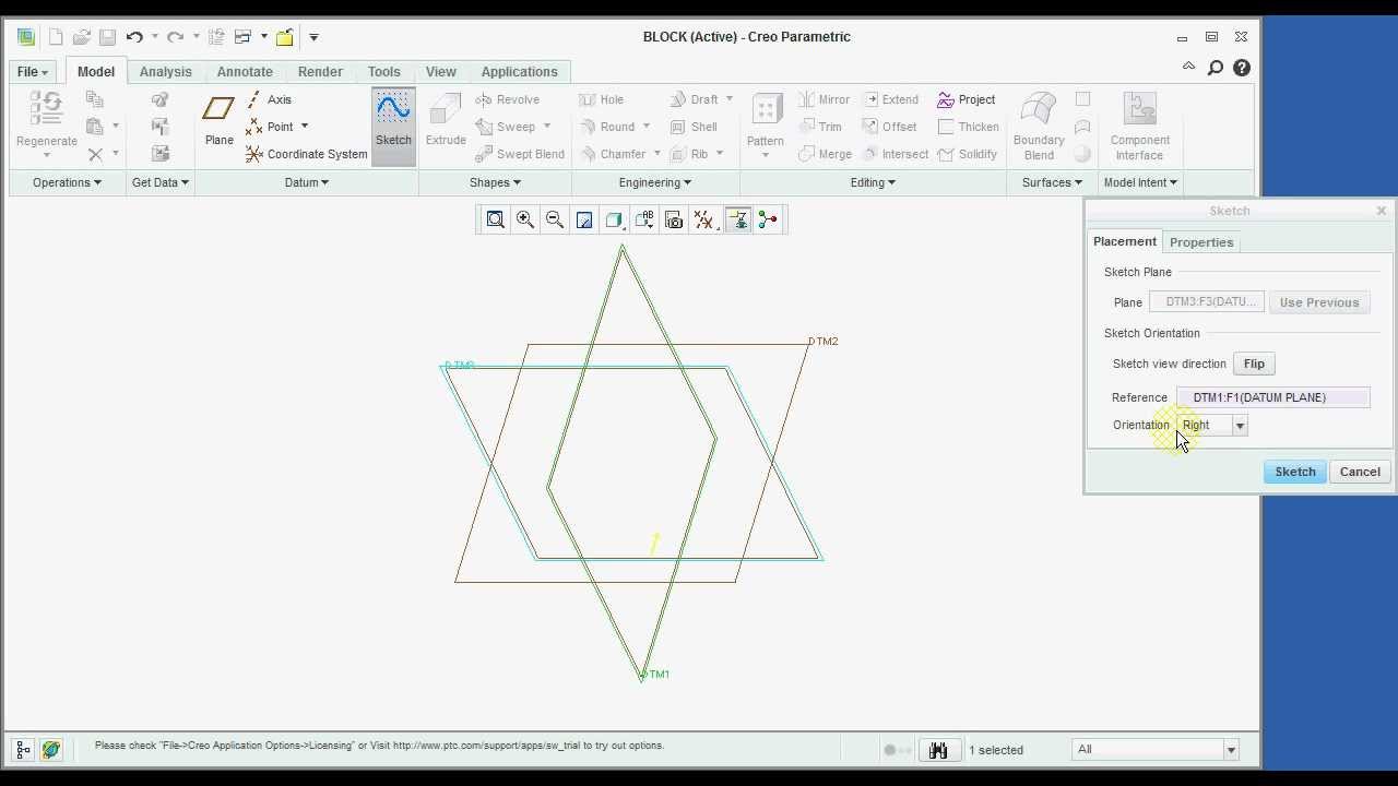
It includes things like the surfaces here, that I can click and manipulate in all the different parts. On the other hand, there's the procedural representation of the model, which is over here in our model tree. Essentially, what it is, is it's a recipe showing how this model, or how this assembly was built step-by-step. So what we can do is, here looking from the assembly level, if I pick on individual pieces of the model, for instance, the bike frame, the wheel assembly, it will highlight the min the graphics area. But if I further expand on a piece, such as this bike crank here, I can actually see the procedures that were taken step-by-step into how to create that part.So here we have our graphical representation of the model, and there's a few different ways that we can interact with it. One way, is just by left clicking on different parts, or features, we can see them highlighted, both in the procedural representation, or the model tree on the left. But also in our graphics area as we click through them. So there's a few different ways we can manipulate this. One is by just clicking on it and dragging, to highlight different parts, like so. We can zoom in by using our middle scroll wheel. We can also rotate, by clicking the middle scroll wheel and dragging. From there if we shift, middle-click, we pan, so that's the ability to move the model left-right, up-down and so on and so forth. And then beyond that, if there's any moving parts, or kinematic constraints in the model, if we control-alt-left click,you can see that we can actually move the model through its constraints. In other words, let's say that we built a gear train, or a rack and pinion, or some other mechanical constraint.
By doing control-alt-left click, we're able to move the model through those constraints. Another key area of Creo,is the graphics tool bar, located at the top for our model. The in-graphics tool bar is this bar, that is right above our model, whenever we're working with it in Creo. And there's a few key features that can really help us as we're working through Creo on it. One of the first key features of the in-graphics tool bar is this refit option. So a lot of times we can be working with a model, and let's say that we zoom in super super far, or we end up going super far out, and we have no idea where our model is. I've lost it, what am I going to do? This option up here, refit, if I click it, snaps me back to having the model in the center of the screen. It's super useful, I use it all the time, and is definitely one of the most helpful options in Creo. Another option on the in-graphics toolbar, is our display style. I use this one a lot. There's several different options here. By default, you're probably gonna be set to just shading, as a display style. But, I often use shading with edges which essentially, what it does is, if we have it selected, each and every edge on the model will be colored in black by default. So I can toggle between these to show you. Here, we see one smooth surface, and it can be kind of hard to pick out where an edge is. Unless, we have shading with edges selected. Another option in the in-graphics toolbar, is shading with reflections. Which basically gives us a really nice smooth, polished rendering option,with a shadow down below, and a reflection. Another key piece of the in-graphics toolbar, is our display filters. What the display filters allow us to do is, toggle on and off our datum's. Datum's are nothing but are the pieces of geometry like planes, axis, points, coordinate systems, that can help us as references, for creating new geometry. If we look up, in our in-graphics tool bar, you can see plane display, by clicking those little toggle on and off. Same thing with axis. Same thing with points. Same thing with coordinate systems. So with all of them hidden, I'm left with just the model on screen. The next thing I want to talk about is the spin center. Which is not displayed in the toolbar, or on screen right now. To show the spin center, go up to your toolbar and right click. A drop-down menu will appear. Scroll down and click here,to show the spin center. Now that we can see the spin center, displayed in the toolbar,let's talk about what it does. So, you can see it as the last option here, before our simulate options, and it's highlighted on screen right here. What the spin center is, is it finds the geometric center of our model, and by default if it's enabled, when I go to rotate the model, I will always rotate about that spin center. If I toggle it off, what that does is, now whenever I go to rotate the model, it's going to rotate about wherever I click. So for instance, if I click over here, it's going to rotate about that point. If I click over here, it's going to rotate about that point, as opposed to if the spin center is enabled, it's going to rotate about the middle of the model every time. Another key area of Creo, is the tabs at the top of our command toolbar. By default, we have a number of different tabs. Starting with file, model,analysis, live simulation, annotate, mannequin, tools, view, framework, applications and photo. One of the first tabs we're gonna touch on is the analysis tab.
So it's right over here, and this tab includes a lot of different ways that we can basically perform analysis on our model or gather data. Whether that is doing a measurement, such as distance between two points on our model. So for instance, I can measure the distance between the spokes on the wheel and see that it's 74 inches. I can also do mass analysis, and a lot of other forms of gathering data on this model. Next up, is our tools tab. So over here, we have a lot of different options, some of which you may be familiar with such as, component interface or relations. Other ones are newer, such as our augmented reality options. So starting in Creo, we have this augmented reality suite that is included for free with Creo. What that allows us to do is place a target, such as a spatial target, or a thing mark underneath our model, and then from there we can actually publish it to the cloud, where you can share this design with friends, coworkers, that sort of thing. Get their feedback on the model. And it's a really great way to share your designs, and collaborate with others.
Before finishing up, I want to touch on a quick tip, for working between models,closing, and saving your models. If we want to close our model but continue working in Creo, one of the best ways to do it is to click this little X, up here, in the top left that says close. And now our model is gone and if I want to open up a different assembly or a part, I can do so without having to switch between the two. But, let's say for a second that I did that accidentally, and I haven't saved my work, and I need to get it back and I'm panicking. Fear not, Creo actually has a built-in safeguard for this. So as long as Creo is still running, and I haven't completely X'd out of it, I can still get my work back. And I can do that by going to in session, over here on the left, and you'll see everything that I had open. So, what I was just working on was this cool bike assembly. And If I double click that, you'll see that all my work is still there, my target from the last tip that I gave is there, and I'm ready to continue working. Now, let's say that I am done working, I've saved my work and I want to close out but I also need to open some new things, and there's overlapping references or I want to close out of this assembly completely. What I can do, is I can go over and close the model, and then, what I want to do to clear out the memory of Creo, and to start something totally new, is I'm gonna click this erase not displayed. And you'll see that in here, erase not displayed will show all the things that I have opened and if I'm okay with getting rid of those, I'll hit OK. The memory is totally cleared out. Now, if I were to go to in session, there's nothing there, and I'm ready to open something completely new